Electrical resistance is the property of a material to resist
the passage of electric current through the material. If a voltage,
sometimes called a potential or electromotive force, is applied
to two sides of a chunk of material, such as wire, a piece of
rock, or an electrical appliance, electric current flows through
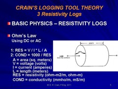
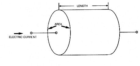
the material. The resistance is defined by Ohm's Law (Georg Ohm,
1827), for direct current (DC) systems, as the ratio of the voltage
applied to the current that flows: Where:
It is interesting to note that the units of measurement for
electrical potential, current, and resistance (volt, ampere, ohm
respectively) were not established until 1863, some 36 years
after Ohm's publication. Prior to this date, and for some time
afterward, more than a dozen units of measurement of resistance
were in use by the infant science of telegraphy, including such
arcane terms as a "German mile", referring to a particular
length of a wire of a particular composition and cross-sectional
area. Where: This looks like Ohm's Law but V and I are vectors represented by complex numbers, so Z is also a complex number. Reactive and capacitive elements in the circuit cause phase shifts between V and I. Z will not be the same as R except in purely resistive circuits. The term "rms" means "root mean square", a method for averaging the absolute values of instantaneous voltage or current over time to obtain a useful value with a meter. A pure sine wave AC voltage of 10 volts rms will have a peak voltage of +/-14.1 volts. The current in a DC circuit is dissipated as heat in the resistor, but only the real component of the complex current is dissipated in an AC system. The imaginary component is converted to a magnetic field in the reactive element. Schlumberger and Lane Wells used DC circuits in their Electrical Logs (actually an alternating DC square wave to prevent polarization of the electrodes). Halliburton and Welex used AC circuits. Given identical electrode arrangements, both would give identical results in an infinite homogenous rock, but thin beds or laminated rocks could provide capacitive effects, detrimental to the AC system.
Where:
Conductance
is the inverse of resistance: Where: Units of conductance are measured in Siemens, named after an early electrical pioneer. The previous name of the unit of conductance was mho, the reverse spelling of Ohm. Conductivity
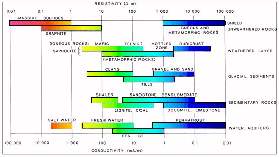
is the inverse of resistivity: Where: The
units of conductivity are Siemens-meters per square meter, or
Siemens/meter (abbreviated S/m). The old name was mho/meter. In
well logging, conductivity is usually given in milli-mho/m or
milli-Siemens/m (mS/m), where milli stands for 1/1000, so the
equation in common use is:. Many people neglect to write or say the "per meter" part of the units when referring to conductivity and the "meter" part of resistivity. Do not confuse resistivity with resistance just because the units have been incorrectly or inadvertently abbreviated. The word "ohm" was often abbreviated with the Greek letter omega (Ω).
The
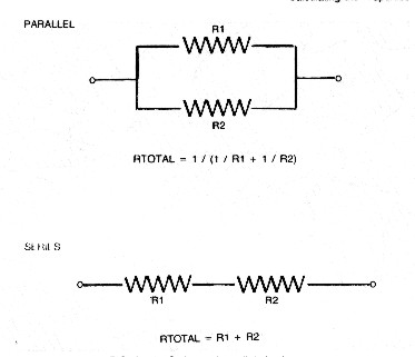
total resistance of resistances connected in parallel is the inverse
of the sum of the inverse of each resistance. This
is more easily seen as the inverse of the sum of the conductance. These relationships are laws of physics within the pressure and temperature domain of interest to log analysts. Superconductivity does not occur in our realm. Resistivity is summed in the same manner as resistance - that is, the laws for series and parallel circuits must be obeyed.
RTOTAL
= 1 + 10 = 11 ohm RES1
= 1 ohm-m RESTOTAL
= 1 + 10 = 11 ohm-m
RTOTAL
= 1 / (1 / 1 + 1 / 10) = 0.9 ohm RES1
= 1 ohm-m RESTOTAL
= 0.90 ohm-m |
|
||
|
Page Views ---- Since 01 Jan 2015
Copyright 2023 by Accessible Petrophysics Ltd. CPH Logo, "CPH", "CPH Gold Member", "CPH Platinum Member", "Crain's Rules", "Meta/Log", "Computer-Ready-Math", "Petro/Fusion Scripts" are Trademarks of the Author |
|||

|
||
| Site Navigation | BASIC PHYSICS RESISTIVITY OHM'S LAW and KIRCHOFF'S LAWS | Quick Links |