Fracture porosity is found accurately only by processing the formation micro-scanner curves for fracture aperture and fracture frequency (fracture intensity). Reservoir matrix porosity and permeability, including that attributed to fracture related (solution) porosity, can be found by normal porosity calculation methods.
Reservoir
simulation software that accounts for the fracture system is often
termed a “dual porosity” model. While this is strictly
true, it would be better to think of them as “dual permeability”
models, since the fracture permeability fed by the matrix or reservoir
permeability is far more important than the relative storage capacity
of the fractures and matrix porosity. A reservoir with only fracture
porosity is quickly depleted; a decent reservoir in the matrix
rock feeding into fractures will last much longer.
Fractures are caused by stress in the formation, which in turn usually derives from tectonic forces such as folds and faults. These are termed natural fractures, as opposed to induced fractures. Induced fractures are created by drilling stress or by purposely fracturing a reservoir by hydraulic pressure from surface equipment. Both kinds of fractures are economically important. Induced fractures may connect the wellbore to natural fractures that would otherwise not contribute to flow capacity.
Fracture aperture exaggeration on acoustic image logs is even more severe and these logs probably should not be used for aperture estimation. These
visual difficulties can be overcome with a post-processing technique
that uses a resistivity inversion model and the mud filtrate
resistivity to calculate aperture, independent of any visual
artifacts.
The algorithm
is based on the concept that higher electrical conductivity means a larger
open fracture. The fracture aperture and fracture frequency can
be combined to obtain fracture porosity and fracture permeability. Where:
Note: Equations 2, 3, and 4 give identical results.
Df = 10 fractures per meter These examples represent well fractured reservoirs. You can see that the volume of hydrocarbon is very small but the permeability is very high. These examples represent well fractured reservoirs. You can see that the volume of hydrocarbon is very small but the permeability is very high. If
you believe that the phrase “fracture porosity” is
a literal definition, then this porosity will usually be pretty
small - in the order of 0.0001 to 0.01 fractional porosity (0.01
to 1.0%). If you believe that the phrase includes vuggy and solution
porosity related to the presence of fractures, then the value
could be much higher. The important thing is to recognize that
there are two definitions for “fracture porosity”.
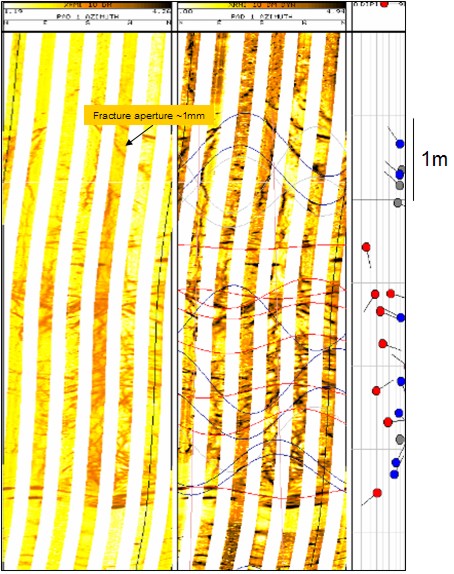
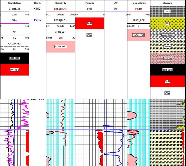
A more accurate approach is based on finite element analysis of the resistivity image data. as described in "Fracture Apertures from Electrical Borehole Scans", S. M. Luthi and P. Souhaite, Geophysics, Vo1.55, No.7, July, 1990, pp.821-833. The math is beyond me and beyond the scope of this article. The method is available from some service companies. An example of a fracture aperture log from a program called Frac-View is shown below.
|
|
||
|
Page Views ---- Since 01 Jan 2015
Copyright 2023 by Accessible Petrophysics Ltd. CPH Logo, "CPH", "CPH Gold Member", "CPH Platinum Member", "Crain's Rules", "Meta/Log", "Computer-Ready-Math", "Petro/Fusion Scripts" are Trademarks of the Author |
|||

|
||
| Site Navigation | POROSITY FRACTURE APERTURE MODEL | Quick Links |