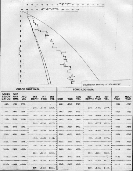
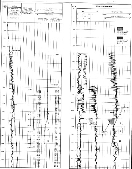
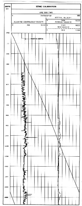
Older check shot (seismic reference survey) data should be used with extreme care. Experience has shown that time breaks and first break times are often difficult to pick and adjusting the log to such data is sometimes worthless. This problem is complicated further in deviated holes. Modern vertical seismic profiles and multi-geophone borehole seismic strings suffer from fewer problems than checkshot surveys because they use digital timing circuits and digital data recording. Recent advances have made it possible to use a series of geophones spaced equally along a cable. More flexibility in geophone placement and closer spacing between recordings is achieved with this approach. On early versions, recording was analog so only first breaks were picked to obtain travel time and hence velocity to a depth. Currently, vertical seismic profiles are made, which record the full seismic trace received downhole at each detector. Automatic first break detection provides the time-velocity-depth data, and a properly processed display of traces is a relatively noise free seismic section near the wellbore. The recorded travel times are used to calibrate the sonic log, which then becomes the basic seismic calibration reference. A time versus depth plot is produced from these data. The calibrated sonic and the density logs are used to construct a synthetic seismogram, which allows identification of reflecting horizons by reference to the seismic response at the wellbore.
The
tool lowered into the borehole consists of: At
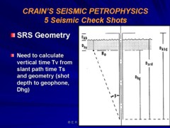
the surface, there will be: The anchored geophone permits releasing cable tension, thus eliminating transmission of much of the surface generated noise. This allows the use of an air gun as a power source thereby obviating explosives and all the attendant safety hazards and logistical complications. The entire well shooting operation can be carried out by the same crew that performs the logging operation thus simplifying personnel movements. Surveys can be run in open or cased (single string) hole. The geometry of an SRS survey is shown below. The calculations take raw arrival times (slant path) and convert them to vertical (straight ray) paths.
For
straight hole:
In
either case:
Where: |
|
||
|
Page Views ---- Since 01 Jan 2015
Copyright 2023 by Accessible Petrophysics Ltd. CPH Logo, "CPH", "CPH Gold Member", "CPH Platinum Member", "Crain's Rules", "Meta/Log", "Computer-Ready-Math", "Petro/Fusion Scripts" are Trademarks of the Author |
|||

|
||
| Site Navigation | LOG EDITING SEISMIC REFERENCE SURVEYS (SEISMIC CHECK SHOTS) | Quick Links |
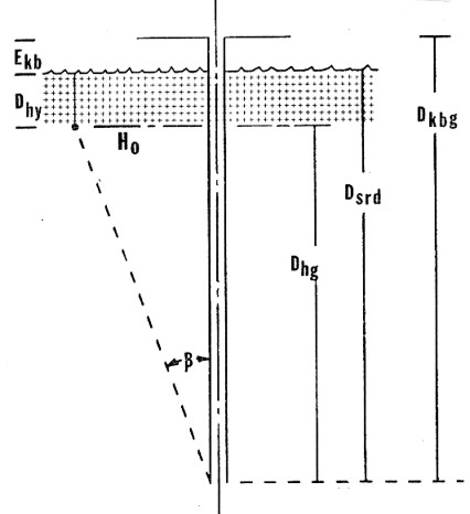 Checkshot geometry
==>
Checkshot geometry
==>