|
 Classic
Dipmeter Patterns On Arrow Plots
Classic
Dipmeter Patterns On Arrow Plots
There are numerous sets of classic dipmeter patterns published
by the service companies. The set from Western Atlas is included
here, with captions, to assist you in learning to analyze patterns,
especially those for which there is more than one interpretation.
They were chosen over others because they include an SP or GR
curve shape and a lithologic cross section on the same drawing
as the dipmeter data for each example.
Trying
to analyze a dipmeter without knowing which rocks are shales and
which are reservoirs is pointless. Don't ignore the evidence from
the other available logs. Don't try to analyze dipmeters in isolation
with a blindfold hiding the other logs; use an integrated approach
incorporating all available data.
Since some structural patterns can be confused
with some stratigraphic ones, you may need to review the stratigraphic
patterns before settling on the final interpretation. Remember
that structural dips are found at bed boundaries and inside
shales. Stratigraphic dips are found inside the sandstone or
carbonate reservoirs, not outside them.
The
illustrations and text in this section are from "Diplog Interpretation",
published by Dresser Atlas (now Baker Atlas) in 1984.
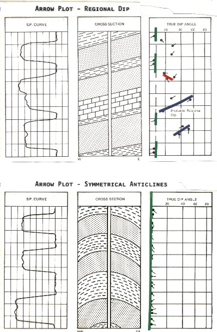
Regional Dip and Symmetrical Anticline
Regional
dip is indicated by the dips recorded in these shale sections.
The sands are cross-bedded and the limestone fractured, giving
readings which cannot be interpreted as regional dip. In many
instances, only one of each 15 or 20 dips reflects actual structural
dip.
An
anticline well drilled through the crest of an anticline or the
trough of a syncline would exhibit low angle dips. these dips
can be low enough to give low angle dip scatter. Wells drilled
on either flank of this fold will indicate larger and more consistent
dips. These dips will reflect the structural dip at the point
where the well cuts the formation.
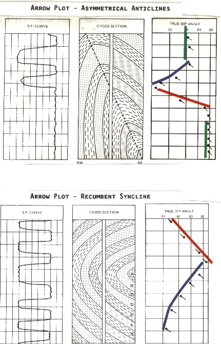
Asymmetrical Anticline and Recumbent Syncline
The
direction of dip in this asymmetrical anticline decreases until
the crestal plane of the structure is encountered then increases
to nearly vertical as the well bore cuts the formations essentially
parallel to the bedding planes. Other overturned anticlines will
produce different Diplog patterns depending upon the amount of
overturning present.
Recumbent
syncline bed "A" is the youngest bed. Beds "B",
"C", "D", etc., become progressively older.
A recumbent anticline would be the same except that bed "A"
would be the oldest bed with the others becoming progressively
younger.
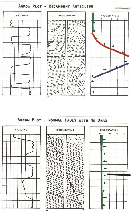
Recumbent Anticline and Normal Fault -No Drag
Recumbent
anticline dip increases to 90 degrees where the borehole crosses
the vertical section of the fold. Below this the dips are reduced
and would usually dip in a direction approximately 90 degrees
to that above the axial plane of the fold.
Normal
fault with no bedding plane distortion. Fault is not apparent
from Diplog and must be located by other methods. If only one
well is drilled in an area, this type of fault will normally not
be found. Bed "E" has been cut out where the borehole
crosses. If this is the zone of interest, the well must be sidetracked
or re-drilled to encounter the objective horizon.
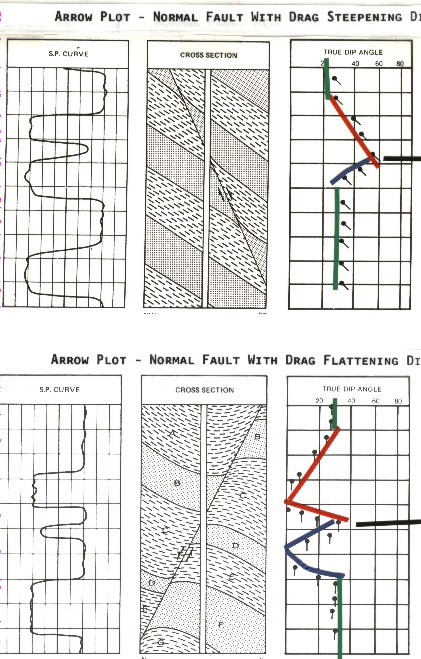
Normal Fault with Drag
Normal
fault with fault plane dipping same direction as formation bedding
planes and exhibiting a small drag zone near the fault plane.
Normal
fault with fault plane dipping opposite to the dip of the formations
illustrating drag into the fault plane.
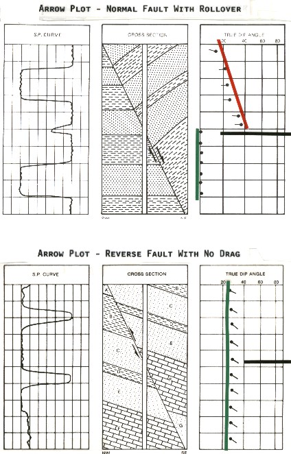
Normal Fault With Rollover and Reverse Fault
With No Drag
Normal
fault with rollover. This is a pattern typical of growth faults
which frequently exhibit reverse drag or rollover. These rollover
anticlines are important hydrocarbon traps along the U.S. Gulf
Coast.
Reverse
fault with no bedding plane deformation. Beds "D" and
"E" ad parts of "C" and "F" have
been repeated. Repetition of beds is good evidence that a fault
is a reverse fault.
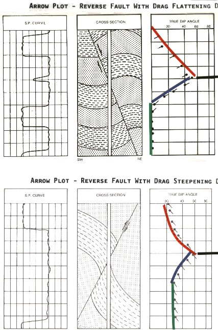
Reverse Faults With Drag
Reverse
fault with fault plane dips in the same direction as the dip of
the beds. Drag zone in both fault blocks.
Reverse
fault with fault plane dips opposite the dip of the formations.
Drag zone in both fault blocks. Sandstone is assumed to be free
from cross-bedding in this illustration.
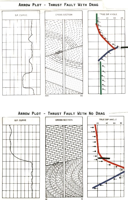
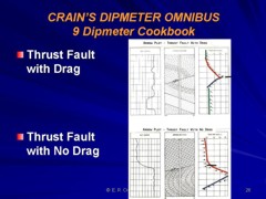
Thrust Faults
Thrust
fault with marked bedding plane distortion on both sides of the
fault plane. This same pattern could be generated by a recumbent
or overturned fold. In some areas, both thrust faulting and overturned
folds are commonly encountered. Obviously, the correct interpretation
of this arrow pattern depends to a considerable extent upon knowledge
of the regional and local geology.
Thrust
fault with drag on bottom block and little or no deformation of
the beds above the fault plane. This type of response is shown
by the Lewis overthrust which has formed Chief Mountain in Glacier
National Park, Montana.
You
should study these patterns carefully, comparing patterns from
various structures to define differences and similarities.
|