Petrophysical Training
Licenses
|
 PERFORATING BASICS
Portions of this page are from Petroleum Engineer's Handbook
(PEH) online version.
A
perforation, in the context of oil or gas production, refers
to a hole through the casing and cement sheath into the
reservoir rock, allowing fluids to flow into the wellbore.
The depth interval to be perforated is determined by the
results of a competent petrophysical analysis of potential
reservoirs, aided by local field experience and regional
geological knowledge.
Perforations are created in a wellbore by specially designed
explosives carried by a perforating tool, sometimes called a
perforating gun.
Where possible, perforating tools are run on wireline. After
placing the perforating tool at the desired depth,
electrical signals from the surface fire the explosives. In
deviated and horizontal wells, coiled tubing may be used to
convey the tool. Newer technologies allow the tools to be
run on slickline, using embedded fiber optic lines to
trigger tool operation. Less commonly, they can be run on
tubing or as part of the casing string.
There are two main types of wireline perforators. One
uses black powder with steel bullets, developed in the 1930s, to
“shoot” holes through the casing. The other, using shaped charges
developed from military “armour-piercing” science, became available
after 1946; this is the most common perforating tool today.
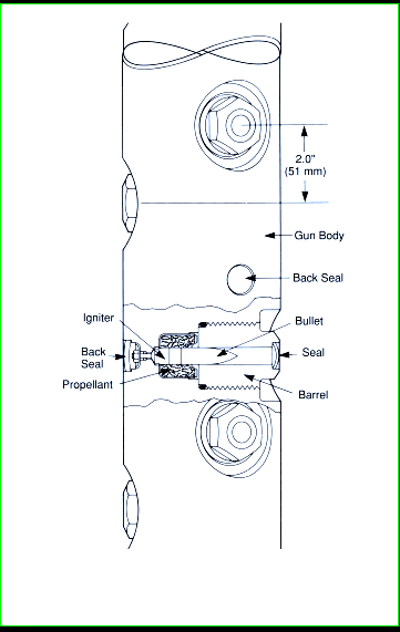
Typical tools create holes of 6 to 24 inches in depth by about 1/2
inch in diameter, with shaped charges giving deeper penetration.
Shots are spaced a few inches to a foot apart, often 4 shots per
foot (4 spf) or 13 shots per meter (13 spm).
The bullet gun creates some microfractures around the perforation
in the rock, increasing near wellbore permeability. Shaped charges
reduce near wellbore permeability, so a small acid or hydraulic
fracture stimulation is often applied to mitigate this drawback.
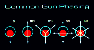
The radial angle between the shots is called the phasing. The most
common phasings are 0°, 180°, 120°, 90°, and 60°. A hundred or more
perforations can be made in a single run into a well.
Alternatives to explosives also were implemented, normally with an
abrasive slurry of material such as frac sand and a carrier liquid.
Abrasive perforating methods are slower, require a rig, and contain
several wear points in the treating equipment.
 Planning,
tool selection, and wellsite implementation are critical steps to a
successful perforating job. Planning,
tool selection, and wellsite implementation are critical steps to a
successful perforating job.
The following tool descriptions are highly condensed from a
Wikipedia article, with some editing for clarity.
 Bullet gun perforators
Projectiles (bullets) from these perforating tools
must penetrate the casing, cement, and formation. Penetration is
easiest in low alloy, thin wall pipe. Penetration in higher strength
casing and harder formations is more difficult in most cases and not
feasible in others. When successful, the bullet creates a very round
entrance hole but may create a hole with sharp internal burrs.
Perforation length drops sharply with increasing formation
strength, with extremes of 15 inches in soft chalk to only 2 to 3
inches in dolomite. In contrast to shaped-charge perforating,
however, bullets often shatter the rock rather than smoothly push
back and compact the rock in their path. The shattering can be a
definite advantage when the cracking improves the permeability next
to the perforation.
  Shaped charge perforators
These perforators come in two basic flavours:
retrievable hollow carriers and expendable strip carriers.
<== Expendable
shaped charge carrier (left), Hollow shaped charge carrier (right)
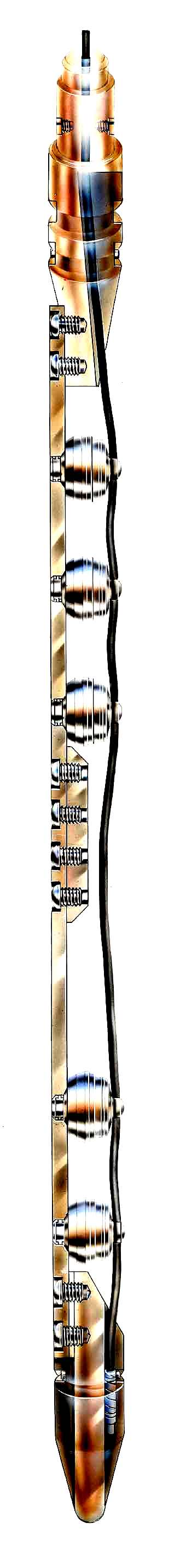
Retrievable hollow carrier perforators are tubes that contain the
shaped charges and ignition system, and can be run either on
wireline or tubing. They can carry large charges and the tool mass
absorbs some of the recoil, minimizing casing damage. The carrier
contains most of the debris from the charge and alignment system,
leaving little trash at bottom hole.
They can be small size, able to pass through tubing and
restrictions, or larger sizes that are run through casing, conveyed
by either wireline, work string, or the production tubing. Both
reusable and single use tools are offered.
Hollow carriers, depending on their diameter and design, may be
loaded with 1 to 27 shots/ft and have all the commonly used phase
angles, as well as specialty phasings.
On larger diameter, thick wall hollow carriers, there is much less
distortion caused by the shots than on the small, thin wall through
tubing tools. In wells with tight clearance between carrier and
tubulars, the amount of distortion of the tool should be determined
from the service company before use. Some tools have shallow
scallops at the shot locations so that shot distortion will not
exceed the nominal tool diameter.
Expendable Strip Perforators have shaped charges that are exposed to
well fluids and pressures. They are popular for through tubing
applications, but are more vulnerable to damage. Without the bulk of
the hollow carrier body, larger charges can be run through any given
small or buckled tubing restriction.
The charges are linked together by a common strip, wire/cable, or a
linked body design. The expendable tools force the casing to endure
a much higher explosive load during firing because the recoil is not
contained in a sacrificial shell as in a hollow carrier. Casing
splits are sometimes seen after perforating in cased holes with poor
cement or low-strength casing.
Expendable tools are used because their perforating performance is
significantly better than hollow-carrier tools in the smaller
diameters.
When the charges are fired, some or all the linking materials, as
well as the charge capsule remnants, are left in the hole.
Shaped
charge concepts
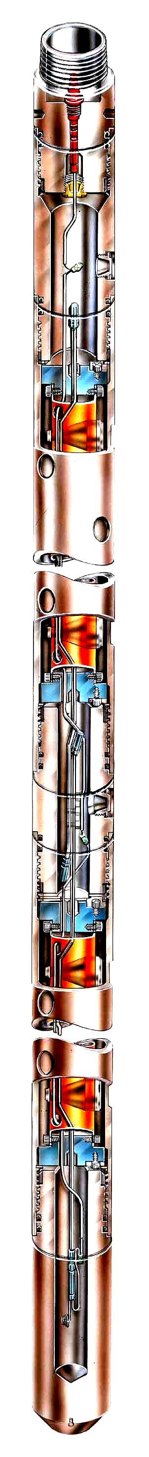
The shaped charge or “jet” perforator
uses a small amount of high explosive and a carefully shaped case
and liner to create a focused pressure wave that is highly effective
in piercing steel, cement, and rock. The jet is formed through a
highly critical but reliable sequence of events, beginning with the
firing of the initiator or detonator cap, which ignites the
detonation cord running through each shaped charge, followed by the
initiation of each charge.
As the explosive front moves through the charge, it
strikes the apex of the liner deforming the liner and fluidizing
part of its mass into a focused jet that punches a hole through the
material in its path.
As the jet forms, it stretches out with the jet tip approaching
speeds of 6100 m/s (21,000 ft/sec), and the tail of the jet
traveling at approximately 3,000 m/s (11,000 ft/sec). The jet is not
hot and does not burn or melt anything; it can pierce a book leaving
no scorch marks, just compressed paper around the hole.
Shaped Charge
Carrier
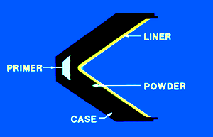
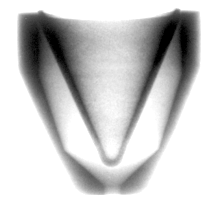
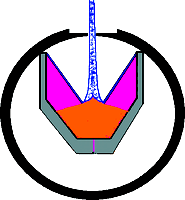
Parts of a shaped charge (left), X-ray of a 20-g charge (middle),
Jet formation (right)
Detonator safety systems
Once on depth, charges are fired
by an initiator or detonator. Any wireline conveyed, hollow carrier
perforator should have a detonator system that will not allow the
charges to fire if the gun is completely or partially filled with
water. If a water filled hollow-carrier gun is fired, the outer body
shell may rupture and result in a fishing or milling job.
Specialized detonators have methods of preventing wet (fluid filled)
gun firing, as well as offering a number of other safety benefits
ranging from resisting stray currents, such as static and radio
energy, to pressure switches that put the tool in safe mode to
prevent accidental surface firing.
Although the standard explosive detonator, also called a blasting
cap, is a mainstay of the construction industry, it is not well
suited to the petroleum industry. Instead, the resistor detonator is
used, incorporating resistors that reduce the possibility of
discharge from low-power electrical signals.
Abrasive perforating methods
Abrasive perforating uses high
volume flow of abrasive laden fluid to erode through the target pipe
or cut it off when the nozzle or tubing string is rotated. Abrasive
impingement of hard particles such as sand on steel can cut through
0.25 to 0.3 in. of casing in a matter of minutes. Perforations in
the casing or even 15 × 1.2 cm (6 in. × 0.5 in.) slots can be formed
within 10 to 20 minutes per slot.
Abrasive methods often use a shaped nozzle that focuses the stream
on the steel surface. The nozzle helps preserve energy, shorten
cutting time, and decrease the effect of clearance distance, but the
nozzle wears with use.
Perforation depths formed by abrasives are typically short because
the returning fluid and solids interfere with the ability of high
pressure fluids to access deeper targets. Depths of 2.5 to 23 cm (1
to more than 8 in.) have been measured in tests performed with
backpressure.
Abrasive perforating in surface targets often produces quicker
cutting and deeper perforation depth, but these tests are not a
valid representation of tool performance in a well. Adding
backpressure on any type of a jetting tool rapidly diminishes its
performance.
Required equipment includes a rig with tubing large enough for the
required rate with minimal friction drop. A fixed nozzle for
perforating or a rotating nozzle for abrasive cutoff is the main
bottomhole assembly.
|
|