Portions of this page are from Petroleum Engineer's Handbook (PEH) online version. Depth is the most important measurement made in relation to well
log data
acquisition. Accurate depth measurements allows for
information to be compared to the wellbore and across
multiple wells in a field. There are several types of data
from geology, drilling measurements, completion and
production operations that use depth as a normalizing tool.
t allows all the phases of a wells life to be correlated to
the reservoir or zone of interest. Small errors will have a
great impact on the success of a well. Therefore, depth
control during logging, completion, and work over is
critical to make sure it is correct and consistent. The main
consideration is appropriate logging speed to reduce variations in
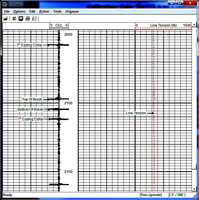
cable tension caused by tool drag. Depth control in a cased hole
operatiom usually involves correlation between one or more cased
hole logs with existing open hole logs. Hence, the speed must be
slow enough that the resolution of events on the gamma ray (GR),
collar locator (CCL), and neutron log (if run) is sufficient to
identify the characteristic log response of the depth interval to be
completed or serviced. Make sure the open hole base log is correct
for the well you are working on.
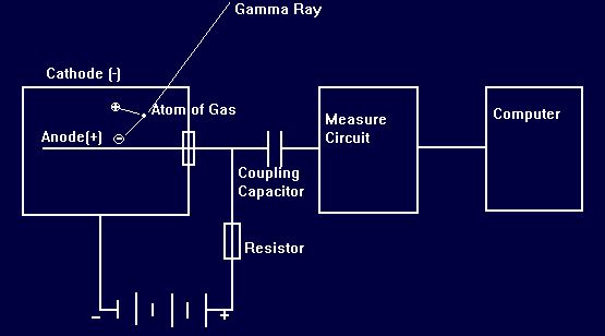
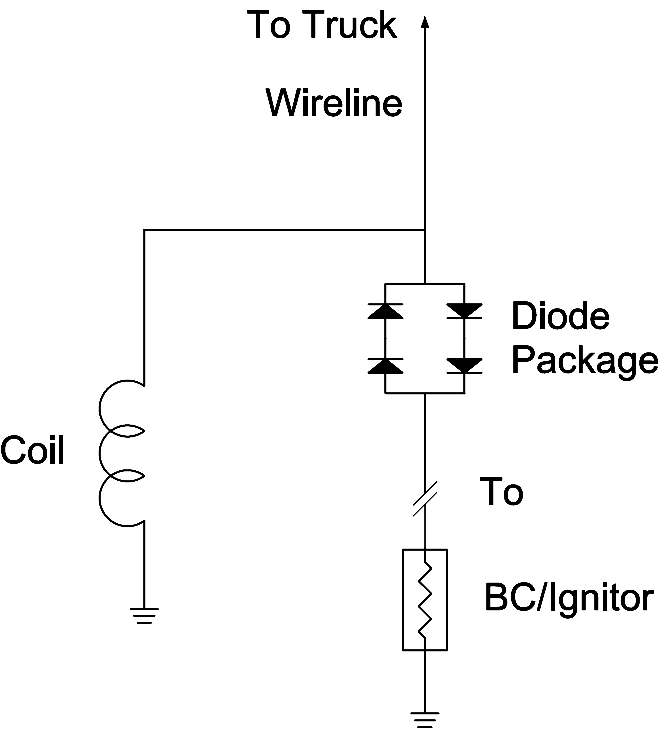
Circuit diagram for a Collar Locator log ==> At this point, what happens to the signal depends on what type of CCL is being used, either powered or non-powered. In the non-powered CCL, the voltage is placed on the wireline and travels up-hole to the logging unit. Diodes prevent the signal from travelling through the mud to the sueface. In the powered CCL, the voltage is passed to an amplifier circuit in the CCL tool and then the amplified signal is placed in the wireline and sent to the surface computer to be processed.
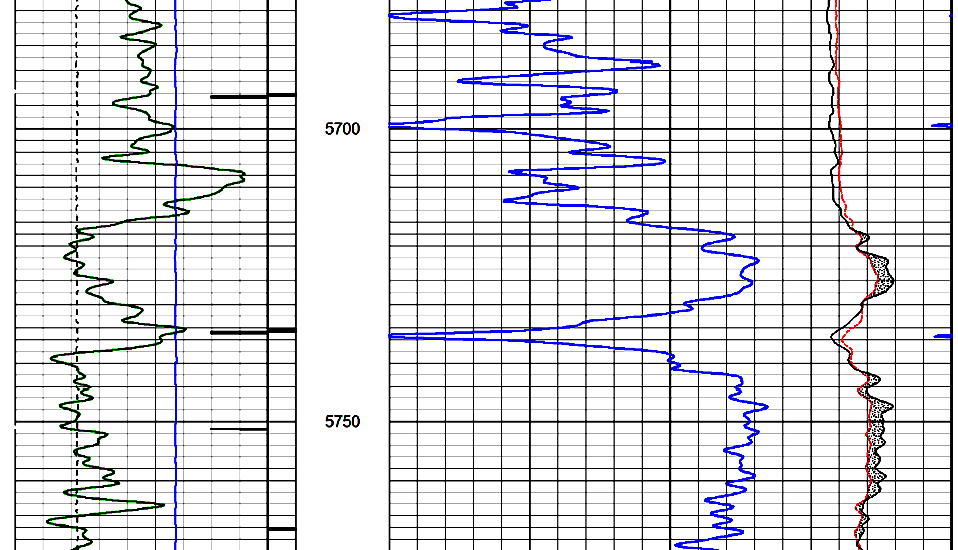
On the log, low GR values arw toward the left side, usually in Track 1. A GR curve spanning Tracks 2 and 3, with low values toward the right, is sometimes presented to aid correlation to open hole porosity logs. A cased hole GR log may be scaled in counts per second (cps) or APIgr Units. The APIgr scale may or may not be calibrated, and if calibrated, may or may not have casing and borehole size corrections applied. Read the log heading carefully. A cased hole neutron log may also be run with a GR / CCL depth control log. It can be scaled in counts per second, APIn Units, or porosity units (% or decinal fraction), spanning Tracks 2 and 3. In all cases, low porosity is toward the right and high porosity and shale to the left. The shape of the
cased hole gamma ray log curve is used to correlate depths with the
open hole logs. The depth recording system in the logging unit is
manually adjusted so that cased hole depths match open hole logs.
Then and only then can the planned completion or work over proceed.
The current produces a voltage drop across a resister. The voltage drop is coupled as a negative pulse into an amplifier circuit, sent up the wireline, detected by the computer and counted over a short time interval. The computer translates the number of pulses into a curve on the log. This type of tool is often called a Gun Gamma Ray as the tool is rugged enough to survive the detonation of perforating guns and other explosive devices.
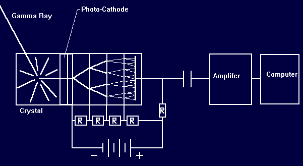
The scintillation gamma ray detector is much more efficient and thus more sensitive than the Geiger-Mueller detector. The detector consists of a sodium iodide crystal and a photomultiplier. When a gamma ray enters the crystal, a photon (a tiny speck of light) is emitted. The photomultiplier amplifies this tiny pulse into a useable electrical signal that can be sent up the wireline to the computer. The crystal degrades with rough handling and shocks so, depending on tool design, it may not be suitable for all cased hole applcations.
Resolve time is the time between two barely recordable pulses. Variation of count
rate due to the random disintegration of radio-active material are
called statistical variations. It is reduced by averaging the raw
output from the GR tool over a specific distance or time interval
using an averaging formula. The longer the filter distance, the less
defined the formation bed boundaries are on the log. Typical filters
are 1 or 2 seconds long and logging speed is set so that this time
represents 2 or 3 feet of travel. G-M detectors need longer time
constants and slower logging speeds to achieve a good quality log.
|
|
||
|
Page Views ---- Since 01 Jun 2020
Copyright 2023 by Accessible Petrophysics Ltd. CPH Logo, "CPH", "CPH Gold Member", "CPH Platinum Member", "Crain's Rules", "Meta/Log", "Computer-Ready-Math", "Petro/Fusion Scripts" are Trademarks of the Author |
|||

|
||
| Site Navigation | THROUGH CASING Depth Control Collar Locator Gamma Ray | Quick Links |
 All
collar locators work on the basis of Faraday's law. Each collar
locator (CCL) has a coil with a magnet located at each end. The
magnets create a fairly large magnetic flux which surrounds the
coil. When a CCL is traveling down hole, the changes of pipe mass at
the end of each pipe joint (the pipe collar) disturbs the flux of
the CCL. As the flux changes, a voltage is created in the coil.
All
collar locators work on the basis of Faraday's law. Each collar
locator (CCL) has a coil with a magnet located at each end. The
magnets create a fairly large magnetic flux which surrounds the
coil. When a CCL is traveling down hole, the changes of pipe mass at
the end of each pipe joint (the pipe collar) disturbs the flux of
the CCL. As the flux changes, a voltage is created in the coil.