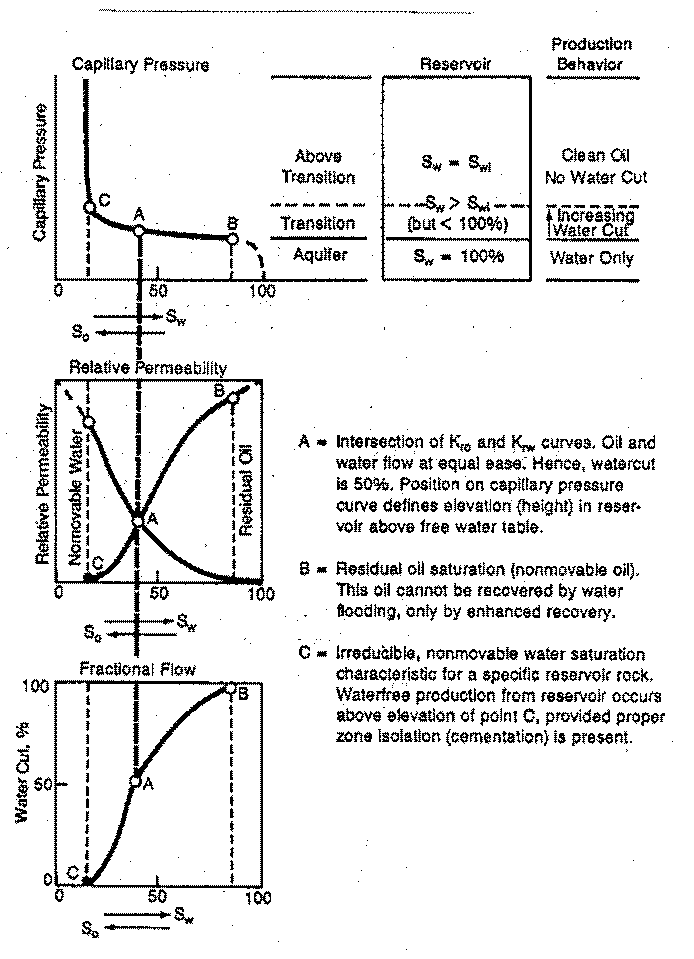
Capillary pressure curves define irreducible water
saturation SWir (vertical
The difference between Sw and SWir, and relative permeability of water and hydrocarbon, determine the water cut. These concepts are best described by the capillary pressure curve and relative permeability curves illustrated above.
Irreducible water saturation is a necessary value for water cut and permeability calculations.
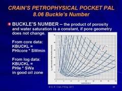
STEP 1: Find Buckles number from special core analysis or from log analysis in a known clean pay zone that produced initially with zero water cut. 1: KBUCKL = PHIe * Sw (in a CLEAN zone that produced initially with no water, or from core data)
STEP 2: Solve for irreducible water saturation in each zone. 2: IF zone is obviously hydrocarbon bearing 3: THEN SWir = Sw 4: OTHERWISE SWir = KBUCKL / PHIe / (1 – Vsh) 5: IF SWir > Sw 6: THEN SWir = Sw
An easier,
but equivalent, model is:
Reference:
· Buckles Number can be found by observing the porosity times water saturation product in pay zones where RW@FT is known, or where a water zone can be used to calibrate RW@FT. Data can also be found from capillary pressure data.
· If Sw is greater than SWir, then the zone will produce with some water cut (if it produces anything at all).
· If Sw is less than SWir, then the Buckles number for the layer is wrong.
· The (1 – Vsh) term can be replaced by (1 – Vsh^2) if needed.
· Calibrate water saturation to core by preparing a porosity vs SWir graph from capillary pressure data. Adjust KBUCKL, Vsh, PHIe until a satisfactory match is achieved.
Sandstones Carbonates KBUCKL Very fine grain Chalky 0.120 Fine grain Cryptocrystalline 0.060 Medium grain Intercrystalline 0.030 Coarse grain Sucrosic 0.020 Conglomerate Fine vuggy 0.010 Unconsolidated Coarse vuggy 0.005 Fractured Fractured 0.001
Gas Shale
0.009 - 0.025
The NMR transform is illustrated below. The matrix and dry clay terms of NMR response are zero. An NMR log run today can display clay bound water (CBW), irreducible water (capillary bound water, BVI), and mobile fluids (hydrocarbon plus water, BVM), also called free fluids or free fluid index (FFI). On older logs, only free fluids (FFI) is recorded and some subtractions, based on other open hole logs, are required.
Nuclear Magnetic Resonance Response to Fluids
7: PHIt = CBW + BVI + BVM 8: PHIe = BVI + BVM
9: SWir = BVI /
(BVI + BVM)
Some or all of the sums defined above may be displayed on the delivered log. Log presentation is far from standard for NMR logs. PHIt and PHIe from NMR do not always agree with that derived from density neutron methods, which see much larger volumes of rock.
For older logs, the BVI measurement was not
possible, so:
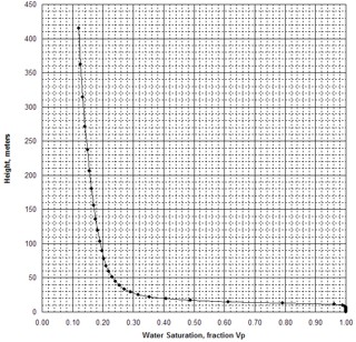
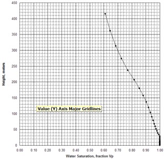
Only sample 1 in the above table behaves close to asymptotically, as in curve A in the schematic illustration at the right. All other samples behave like curves B and C (or worse). The real cap pressure curves for samples 1 and 2 are shown below.
The summary table shows wetting phase saturation
selected by observation of the cap pressure graphs at two different
heights above free water, namely 100 meters and 425 meters in this
example. In this case, the 100 meter data gives water saturations
that we commonly see in petrophysical analysis of well logs in
hydrocarbon bearing Bakken reservoirs in Saskatchewan. This is a
pragmatic way to indicate the water saturation to be expected when a
Bakken reservoir is at or near irreducible water saturation. The
data for the 450 meter case is considerably lower and probably does
not represent reservoir conditions in this region of the Williston
Basin. |
|
||||||||||||||||||||||||||||||||||||||||||||||||||||||||||||||||||||||||||||||||||||||||||||||||||||||||||||||||||||||||||||||||||||||||||||||||||||||||||||||||||||||||||||
|
Page Views ---- Since 01 Jan 2015
Copyright 2023 by Accessible Petrophysics Ltd. CPH Logo, "CPH", "CPH Gold Member", "CPH Platinum Member", "Crain's Rules", "Meta/Log", "Computer-Ready-Math", "Petro/Fusion Scripts" are Trademarks of the Author |
|||||||||||||||||||||||||||||||||||||||||||||||||||||||||||||||||||||||||||||||||||||||||||||||||||||||||||||||||||||||||||||||||||||||||||||||||||||||||||||||||||||||||||||

|
||
| Site Navigation | IRREDUCIBLE WATER SATURATION (SWir) | Quick Links |
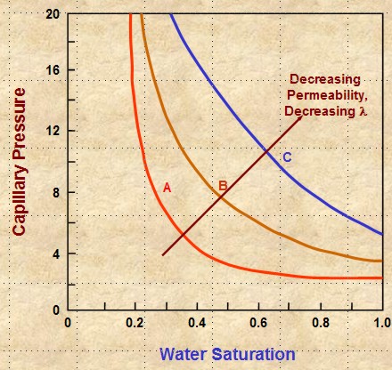 In
higher permeability rock, the cap pressure curve quickly reaches an
asymptote and the minimum saturation usually represents the
irreducible water saturation in an undepleted hydrocarbon reservoir
above the transition zone. In tight rock, the asymptote is seldom
reached, so we pick saturation values from the cap pressure curves
at two heights (or equivalent) Pc values) to represent two extremes
of reservoir condition.
In
higher permeability rock, the cap pressure curve quickly reaches an
asymptote and the minimum saturation usually represents the
irreducible water saturation in an undepleted hydrocarbon reservoir
above the transition zone. In tight rock, the asymptote is seldom
reached, so we pick saturation values from the cap pressure curves
at two heights (or equivalent) Pc values) to represent two extremes
of reservoir condition.