|
 RADIOACTIVE
TRACER LOGGING BASICS
RADIOACTIVE
TRACER LOGGING BASICS
Tracer logs are used to monitor hydraulic
fracture placement in a reservoir and as
a method of determining injection flow
profiles.
Other
processes that can be tagged are gravel-pack
placement, squeeze cementing, acid treatments, and lost
circulation zones.
The most common radioactive tracers are the isotopes
110Ag (silver), 195Au (gold), 135I
(iodine), 192Ir (iridium), 124Sb
(antimony), and 46Sc (scandium).
MONITORING HYDRAULIC FRACTURE
PLACEMENT
In this case, a short-lived
radioactive element is added to the frac fluids or propping
material. Different elements may be introduced at different
times during the fracture placement so that fracture growth
can be assessed versus time. After placement, a gamma ray
log is run, starting some distance below to some distance
above the frac interval. If only one element was used, a
conventional gamma ray tool will suffice. For a
multi-element survey, a spectral gamma ray log is required.
The fracture height and position can be assessed by
observation of the gamma ray curves. The fracture may extend
above and below the perforated interval. Comparison of this
log with a competent petrophysical analysis will help
determine if the frac went up or down into unwanted
territory, for example a water zone below or a gas zone
above the desired oil zone.
Post-frac radioactive tracer log with natural gamma ray in
Track 1 recorded before stimulation. Tracer log in Tracks 2
and 3 shows some placement into both sets of perfs, but also
above upper perfs, possibly due to channel in cement behind
casing.
MONITORING FLUID FLOW
In this case, a specialized production
logging version of the gamma ray tool is used to
monitoring the reduction in tracer material as it moves down
the well. A slug of radioactive tracer is added to the
injection fluid. As the slug moves down the well, several
gamma ray logs are recorded at well defined time intervals.
The position of the slug is seen as a large gamma ray peak
whose size is proportional to the flow rate. A reduction in
the size of the peak indicates a loss of fluid into the
formation. Fluid velocity can be calculated from the time
interval and the distance the peak has moved.
Tracer-loss measurements produce a type of radioactive
tracer log used mainly to give a general idea of fluid flow
in low flow-rate wells. In very low flow-rates, an
alternative technique has been used in which the gamma ray
detector is held stationary at some depth until the slug has
passed. The detector is then moved down to another depth to
observe the slug again. With these data, it is possible to
make quantitative estimates of fluid flow.
The typical tool has a reservoir to hold radioactive
material and a pump section at the top
with two gamma ray detectors below. Once downhole, a slug of
tracer is ejected by the pump. The radioactivity of the slug
is much greater than the natural reservoir radioactivity.
The most commonly used tracer material is an aqueous
solution of sodium iodide, which contains the
isotope iodine 131 with a half-life of 8 days.
The following Sections are based on an article on
PetroWiki.com
TRACER SURVEYS IN INJECTION WELLS
By
tracking the progress of the slug down the wellbore, the
exits of injected flow from the wellbore can be determined,
as well as whether any of the injection, after exiting,
passes through a channel close to the pipe.
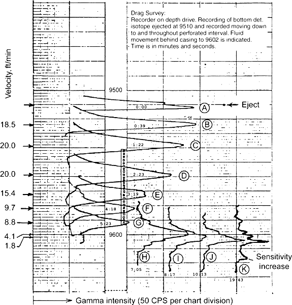
For slug tracking, the logging operator ejects a slug of
tracer from the tool at some distance above the
perforations. After ejection, the tool is run up and down
through the slug to ensure that the slug is uniformly mixed
across the wellbore cross section. Then the tool is lowered
quickly and an upward logging pass is made at constant
logging speed until the slug is detected. The time of
detection of the peak and the depth of the peak are
recorded. Then the tool is quickly lowered again, and
another upward logging pass is made at the constant logging
speed until the slug is detected and again the time
of detection of the peak and the depth of the peak are
recorded. This process is repeated several times, resulting
in a succession of detections of the same slug (see Fig. 1).
As long as the peak progresses downward, there is flow in or
near the wellbore. Once the peak stops, there is no flow in
or near the wellbore below the stopping depth.
For each detection, the area under the trace
and above the common baseline of the traces is proportional
to the percentage of injection still in or near the wellbore.
Generally, only one gamma-ray detector is used for
slug tracking. Slug tracking gives the best overview of where
injection leaves the wellbore and whether, after exiting, any
injection travels in a channel close to the pipe.
The vertical distance (ft) between two successive peaks in total
flow divided by the time (minutes) between detection of the peaks
provides an accurate estimate of the average flow velocity of total
injection.
Multi-pass radioactive tracer log
in 800 bwpd injection well showing slug moving downhole with
decreasing peak amplitude as slug begins to enter perforations.
VELOCITY SHOT
SURVEYS IN
INJECTION WELLS
A velocity shot survey is used in
intervals where greater vertical resolution is desired. With the
tool stationary, a slug of tracer is ejected into the injection
flow. As it passes downward, the slug is first detected by the top
detector and then by the bottom detector, resulting in two traces on
the log. The time interval between the two peaks (travel time) is
inversely related to the velocity of the injection flow.
The ratio of the travel time in total flow to the
travel time at a selected position is the fraction of injection
still in the wellbore at the selected position. However, dividing
the separation between the detectors (ft) by the travel time
(minutes) does not produce the average velocity of flow, as the slug
cannot be uniformly mixed in the flow before it passes the
detectors.
Two detectors are preferred for velocity shots. If
there is only a single detector, there can be timing errors between
initiating ejection of a slug and actual ejection downhole. These
timing errors contaminate the measured travel times.
TRACER SURVEYS IN PRODUCTION WELLS
Fewer applications of tracer logging occur in
production wells. In a true single-phase flow, a slug is tracked for
a while and then disappears uphole. Multiple slugs are used, one for
each producing interval under investigation. Usually, a well is
logged from a bottom, no-flow interval up to an interval of total
flow.
Because of the unusual circulation patterns that can occur in
multiphase flows, tracer results can be misleading
|