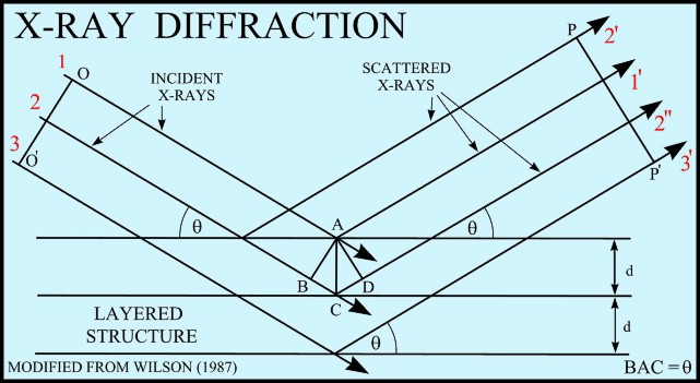
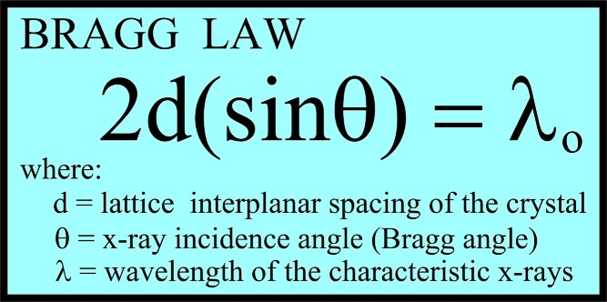
XRD provides a fast and reliable tool for routine mineral identification. XRD is particularly useful for identifying fine-grained minerals and mixtures or intergrowths of minerals, which may not lend themselves to analysis by other techniques. Petrophysicists use XRD values to help calibrate mineral volume calculations derived from well log data. While XRD analysis gives quantitative volume fractions of minerals in a sample, these samples are small and can be high graded intentionally or accidentally. The important result is WHICH minerals are present, with less emphasis on QUANTITY of each mineral. XRD can provide additional information beyond basic identification. If the sample is a mixture, XRD data can be analyzed to determine the proportion of the different minerals present. Other information obtained can include the degree of crystallinity of the minerals present, possible deviations of the minerals from their ideal compositions (presence of element substitutions and solid solutions), the structural state of the minerals (which can be used to deduce temperatures and pressures of formation), and the degree of hydration for minerals that contain water in their structure. Some mineralogical samples analyzed by XRD are too fine grained to be identified by optical light microscopy. XRD does not, however, provide the quantitative compositional data obtained by the electron microprobe or the textural and qualitative compositional data obtained by the scanning electron microscope. The three-dimensional structure of non-amorphous materials, such as minerals, is defined by regular, repeating planes of atoms that form a crystal lattice. When a focused X-ray beam interacts with these planes of atoms, part of the beam is transmitted, part is absorbed by the sample, part is refracted and scattered, and part is diffracted. Diffraction of an X-ray beam by a crystalline solid is analogous to diffraction of light by droplets of water, producing the familiar rainbow. X-rays are diffracted by each mineral differently, depending on what atoms make up the crystal lattice and how these atoms are arranged. XRD has a wide range of applications in geology, material science, environmental science, chemistry, forensic science, and the pharmaceutical industry, among others. At the U.S. Geological Survey, researchers use XRD to characterize geologic materials from a wide variety of settings; below are just a few examples. X-rays are electromagnetic radiation similar to light, but with a much shorter wavelength. They are produced when electrically charged particles of sufficient energy are decelerated. In an X-ray tube, the high voltage maintained across the electrodes draws electrons toward a metal target (the anode). X-rays are produced at the point of impact, and radiate in all directions. Tubes with copper targets, which produce their strongest characteristic radiation at a wavelength of about 1.5 angstroms, are commonly used for geological applications. These X-rays are collimated and directed onto the sample, which has been ground to a fine powder (typically to produce particle sizes of less than 10 microns). A detector detects the X-ray signal; the signal is then processed either by a microprocessor or electronically, converting the signal to a count rate. Changing the angle between the X-ray source, the sample, and the detector at a controlled rate between preset limits creates an X-ray scan, or spectrograph.
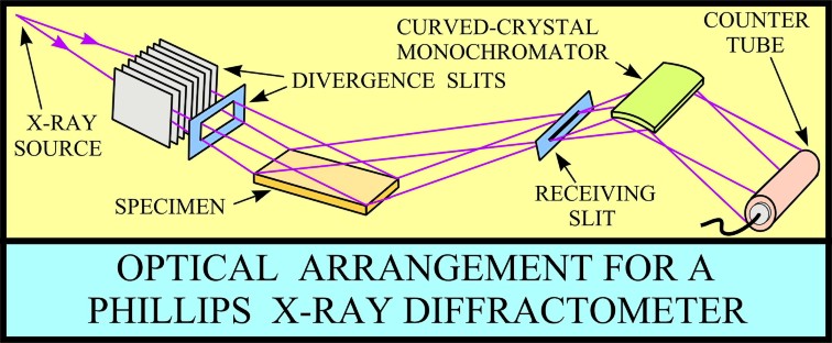
The basic geometry of an
X-ray diffractometer involves a source of monochromatic
radiation and an X-ray detector situated on the circumference of
a graduated circle centered on the powder specimen. Divergent
slits, located between the X-ray source and the specimen, and
divergent slits, located between the specimen and the detector,
limit scattered (non-diffracted) radiation, reduce background
noise, and collimate the radiation. The detector and specimen
holder are mechanically coupled with a goniometer so that a
rotation of the detector through 2x degrees occurs in
conjunction with the rotation of the specimen through x degrees,
a fixed 2:1 ratio.
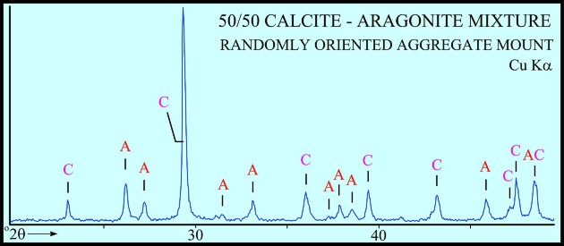
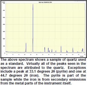
Peaks found on the spectra must have a high enough signal to be discriminated from the background noise. In addition, it is necessary to have secondary peaks that are used to confirm the primary peak as belonging to the particular mineral species in question. As a result, there are practical limitations to the minimum detectability of minerals in the sample. Some minerals may simply be reported as having trace amounts.
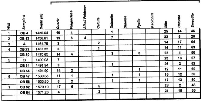
Major uses of XRD data in petrophysical analysis are: mineral identification, quantitative mineral fractions, quantitative clay fractions , and by inference, clay volume and clay / silt ratio. These are used to help calibrate lithology calculations from standard log analysis models. Clay / silt ratio is helpful in calibrating shaly sand analysis and in assessing shale gas prospects. Clay volumes from XRD represent the dry clay mineral only and do not include intraparticle porosity or bound water. Samples used in XRD are very tiny (less than a cubic centimeter) compared to the volume measured by a log, so large statistical variations may be expected. XRD has been used in the oil and gas industry as a routine analysis technique since the early 1960s when cost effective commercial units were introduced to the marketplace. Use of the technique has become commonplace due to its low cost and availability. Sample quality can vary considerably, depending on whether it is a whole rock sample, cuttings or corrosion sample. Homogeneity of the samples can vary considerably as well. A uniform, massive sandstone with well distributed clays and cements will present the least problem while partially cemented sandstones and variable lithology carbonates and cuttings samples represent the most challenging samples. It is recommended that a minimum sample size be in the range of 5 to 10 grams. For normal sample preparation, a 1 gram sample is needed for bulk powder analysis, while 5 grams are needed for clay separates analysis. Normal sampling of bulk samples is accomplished by drying the sample at 60 °C overnight, then fracturing a portion of the bulk rock for use in the pulverizing mill. Samples are normally ground for 20 minutes in the mill until a homogenous powder is obtained. If specified by the client, samples can be crushed then quartered until a representative amount is obtained. This quartered sample is then pulverized until homogeneous. The powder is then packed in a powder mount, against glass, to provide a stable surface for analysis. This will destroy the sample for analysis by most other testing techniques. Special cases would include selection of specific parts of a rock for analysis, for example, mineral nodules of interest. Cuttings can be analyzed as well. Usually a minimal amount of sample is available for analysis, and as a result, hand grinding and packing into a micro powder holder is required. As little as 1 or 2 cuttings can be analyzed in this fashion. The bulk powder holder is then placed into the X-Ray Diffractometer apparatus and the sample is typically scanned from 4 to 60 degrees 2θ (two theta) to produce the spectrum. A copper source tube is used to provide the incident beam of monochromatic X-rays. For clay samples, a 5 gram sample is required in order to get good results from the clay separates. Rock portions are first of all, disaggregated using an agate mortar and pestle with a calgon solution. Suspended clays, silt and sand are then transferred to a glass tube, topped up with calgon solution, agitated and then centrifuged for the appropriate amount of time at given centrifuge speeds to drop out the coarse fraction. The suspended portion is decanted into a clean centrifuge tube, and this is spun at high speed to settle the fine fraction of material. Some labs choose to utilize the less than 5 micron fraction (<5μ) for clay analysis, while others may utilize the <2μ or <1μ fraction. The reason for this is that significant amounts of kaolinite may be settled out of the clay suspension if other than the 5 micron fraction size is used. Kaolinite particles can typically have sizes of 10 - 20 microns. If other than the <5μ fraction is desired, clients should specify what value they want. After settling of the clays, the majority of the supernatant liquid is poured off, and the settled clays are homogenized. A small amount of the clay suspension is then smeared on to a glass slide, and allowed to air dry. The slide is then placed into the goniometer and run typically from 2 to 35 degrees 2θ. The slide will then be removed and placed in a container with glycol vapours at elevated temperature in order to expand sensitive clays. This provides a diagnostic for particular clay types as well as providing an indication of whether or not the clays will be fresh-water sensitive. Heating of samples, on occasion, may be necessary to delineate clay species. Sensitivity to ionic substitution (Na+, Mg++, K+ and Ca++) can also be completed as a special analysis. It should be noted that the term clay analysis in this case refers to sample particle size, and not necessarily mineralogy. As a result, clay results will include such minerals as quartz, feldspars, carbonates and potentially even heavy minerals such as pyrite. If true clay species alone are needed, then recalculation excluding non-clay species will be required. It should be kept in mind that size fractions of non-clay types may be important, particularly where microcrystalline minerals are present, or where dissolution of minerals is or has taken place. Often, these species will show up in the clay trace.
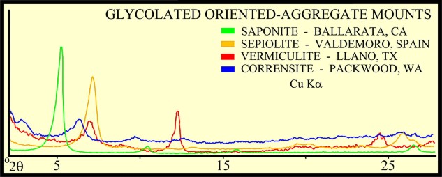
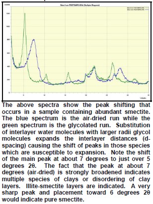
The peak with highest amplitude for a particular mineral is the primary peak. Other secondary peaks are present for most minerals. Identification is based on comparing the peak positions to standard samples with known mineralogy. Some databases contain more than 100,000 samples and software is used to find logical matches to the measured spectrum. Interference between peaks from different minerals sometimes forces the analyst to use secondary or tertiary peaks to aid in identification. Unlikely matches are eliminated by human interpretation and a unique result can usually be obtained. The amplitude of the peaks is used, with scale factors, to estimate the fraction of each mineral present in a sample, illustrated in the example XRD shown below. In the illustration below, the spectra show the peak shifting that occurs in a sample containing abundant smectite. The blue spectrum is the air-dried run while the green spectrum is the glycolated run. Substitution of interlayer water molecules with larger radii glycol molecules expands the interlayer distances causing the shift of peaks in those species which are susceptible to expansion. Note the shift of the main peak at about 7 degrees to just over 5 degrees 2θ. The fact that the peak at about 7 degrees (air-dried) is strongly broadened indicates multiple species of clays or disordering of clay layers. Illite-smectite layers are indicated. A very sharp peak and placement toward 6 degrees 2θ would indicate pure smectite.
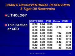
Most sandstones are not pure quartz. This is easy to see on modern logs with PE curves that read well above 1.8. XRD can resolve which minerals are present. In the example below the sand is composed of 71 % quartz, 9% ankerite (an iron rich dolomite), 10% apatite (a phosphate mineral), and 10% pyrite (iron di-sulphide or fool's gold). Note that the grain density is 3.15 gm/cc, considerably higher than pure quartz. As an exercise, you might want to calculate the corresponding PE value from a volume weighted summation of the four PE values of the minerals. See Mineral Properties Table.
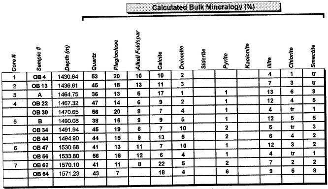
Example XRD Listings
|
|
||
|
Page Views ---- Since 01 Jan 2015
Copyright 2023 by Accessible Petrophysics Ltd. CPH Logo, "CPH", "CPH Gold Member", "CPH Platinum Member", "Crain's Rules", "Meta/Log", "Computer-Ready-Math", "Petro/Fusion Scripts" are Trademarks of the Author |
|||

|
||
| Site Navigation | LAB TECH XRAY DIFFRACTION METHODS | Quick Links |
 If
an incident X-ray beam encounters a crystal lattice, general
scattering occurs. Although most scattering interferes
with itself and is eliminated (destructive interference),
diffraction occurs when scattering in a certain direction is in
phase with scattered rays from other atomic planes. Under this
condition the reflections combine to form new
If
an incident X-ray beam encounters a crystal lattice, general
scattering occurs. Although most scattering interferes
with itself and is eliminated (destructive interference),
diffraction occurs when scattering in a certain direction is in
phase with scattered rays from other atomic planes. Under this
condition the reflections combine to form new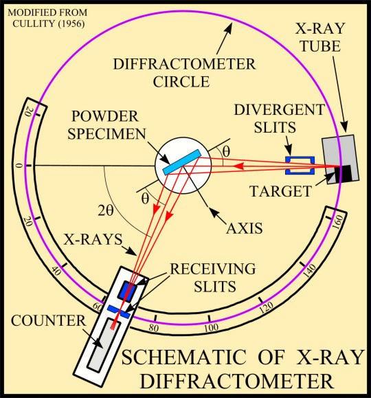