All microresistivity logs require a conductive mud in open hole and do not work in cased hole.
Reference:
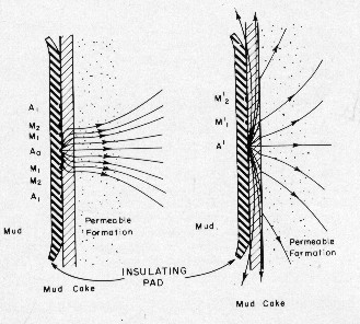
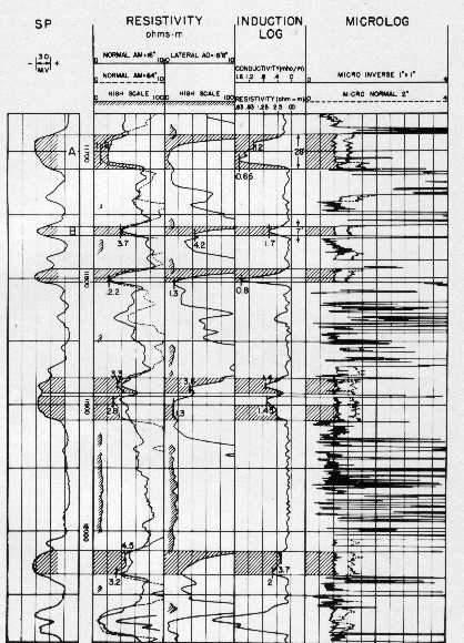
The Microlog tool is a shallow resistivity device mounted in an oil-filled rubber pad which is pressed to the borehole wall during logging by hydraulic pressure electrically controlled from the surface. The pad can be considered as a miniature electrical survey. It records two resistivity curves and a borehole caliper curve. The illustration below shows the Microlog electrode arrangement. Three small button electrodes (A, M1 and M2), spaced one inch apart, are embedded in the center of the insulated pad. A remote electrode, usually near the pad, is also used serving as the current return electrode B and voltage reference electrode N.
Current electrode A is maintained at constant current intensity. The potential difference between electrodes M1 and M2 is used to derive a resistivity curve which is called the micro-inverse and is usually designated R1x1, or simply R1. The electrode arrangement for R1 is equivalent to a lateral-type resistivity tool having a depth of investigation of 1.5 inches. The potential difference between electrode
M2 and the reference or remote electrode is used to derive
a second resistivity curve called the micro-normal, usually
designated R2. The electrode arrangement for R2 is equivalent
to a normal resistivity tool and its 2 inch spacing gives it
a depth of investigation of two to four inches.
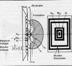
A voltage of constant intensity is applied to the center electrode while a controlled supply of current is applied to the focusing electrodes. The potential difference between the center electrode and the focusing or guard electrodes is maintained at zero by automatic controls. This has the effect of focusing the current into a narrow beam perpendicular to the pad and into the formation. The current beam maintains a uniform shape through the mud cake, spreading out as distance from the pad increases. The potential difference between the center electrode and the remote electrode, in combination with a calibration constant, is a measure of the apparent resistivity of a small volume of the formation near the borehole. The depth of investigation is about three inches from the tool pad. For mud cake less than 3/8 inch thick, the effect of mud cake on tool response is small and can generally be ignored. With flushed zone thickness of two to three inches. The tool reads flushed zone resistivity (Rxo) directly. In wells drilled with low resistivity
(salt) muds, mud cake resistivity is usually quite low compared
to flushed zone resistivity. Under these conditions the mud
cake effect is still small for mud cake thickness greater than
3/8 inch. For fresher muds and higher Rmc/Rxo ratios, the 3/8
inch limitation applies.
The tool design is very similar to the MLLC except for a modified guard electrode arrangement. A second ring of guard electrodes, in addition to those used in the Microlaterolog arrangement, is included. The beam electrode and the guard electrodes also have larger cross-section areas. This configuration is referred to as a shielded guard device. A voltage of constant intensity is applied to the beam electrode. A controlled supply of current is applied to the guard electrode to maintain zero potential between the shield and the beam electrode. The additional focusing shield constricts the current beam from the center electrode even more than with the Microlaterolog tool. A greater thickness of mud cake is thus penetrated with little change in the shape of the current beam from the center electrode.
Measurement of the potential difference between the
center electrode and the remote return electrode in combination
with a calibration constant gives the resistivity of a small
volume of the formation. The improved focusing gives the Proximity
Log a greater depth of investigation and most of the tool response
is received from a distance of six to ten inches from the pad.
Field tests indicate that where moderate to deep invasion exists
and sufficient flushing has occurred, reliable values for the
flushed zone resistivity (Rxo) may be obtained.
The Micro Spherically Focused Log (MSFL) has superseded the Proximity log. It has the general electrode arrangement of the SFL described earlier, placed on a pad in miniature form. The MSFL is the current tool of choice for flushed zone Rxo measurement.
|
|
|||||||||||||||||||||||||||||||||||||||||||||||||||||
|
Page Views ---- Since 01 Jan 2015
Copyright 2023 by Accessible Petrophysics Ltd. CPH Logo, "CPH", "CPH Gold Member", "CPH Platinum Member", "Crain's Rules", "Meta/Log", "Computer-Ready-Math", "Petro/Fusion Scripts" are Trademarks of the Author |
||||||||||||||||||||||||||||||||||||||||||||||||||||||

|
||
| Site Navigation | TOOL PROFILES MICRO RESISTIVITY LOGS | Quick Links |