|
 CASING and TUBING INSPECTION BASICS
Casing
and tubing placed in well bores may suffer from damage due to
corrosion or mechanical distress. Corrosion is caused by natural
electrical currents that flow in the earth, and from man-made
currents from power lines and surface equipment.
Corrosion can be
reduced by cathodic protection systems but not always with
perfectly satisfaction. Corrosion inspection logs and cathodic
protection evaluation logs are widely used in areas where corrosion
is known to be a problem.
Holes in tubing
or casing caused by corrosion can seriously affect production rates
and fluid composition, resulting in economic loss.
Loss of metal may
result in strength loss without holes in the pipe, allowing burst or
collapse, again with serious economic consequences. Bent, squashed,
or oval pipe can impede or prevent the passage of equipment or tools
into and out of the wellbore. Moving parts, such as pump rods, an
cause wear that eventually will cause problems if not repaired in
time.
Although most tubular goods are inspected before running into the
hole, bad pipe has been found in numerous cases after the well
completion has proved unsuccessful. Damage may also occur during
testing of the well, drilling of plugs, or well stimulation.
Un-cemented or poorly cemented casing can be damaged easily with
excessive pressure. The effect on production can be severe and
remediation will be assisted by an accurate diagnosis of the problem
by an adequate inspection program. So
there are lots of potential problems to look for.
The logs offer precise depth correlation when
recorded with gamma ray or casing collar locator logs.
The
following descriptions are condensed from the 1999 Schlumberger
Services Catalog. Equivalent logging tools are available from all
major ,and many smaller, service companies.
CASING INSPECTION with CEMENT MAPPING LOGS
Cement evaluation tools are
traditionally used to assess cement quality, cement bond, channels,
and cement fill-up using azimuthal ultrasonic transceivers.
These tools also have a corrosion inspection mode, measuring the thickness of the casing
from its resonant
frequency. Simultaneously. the internal dimensions of the casing
are determined from the travel time of sound reflected off the
casing walls. An azimuthal image of the casing inside diameter can
be displayed.
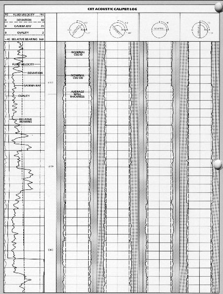
Casing diameter, casing thickness, and ovality
logs from CET tool are use for casing inspection.
Ultrasonic imaging tools evaluate the quality of the cement and determines
both internal and
external casing corrosion. A single rotating sensor emits ultrasonic pulses and measures the resulting resonance. The USI
echo strength
and casing resonance are processed to produce detailed images of cement quality and distribution that can
spot channels as narrow as 1.2 in. Alternate presentations provide
images of casing thickness, internal radius, and internal corrosion.
Casing ovality, kinks, and holes can be observed on the image
logs. The size of the rotating head is chosen appropriately for
the size of the tubular to be surveyed.
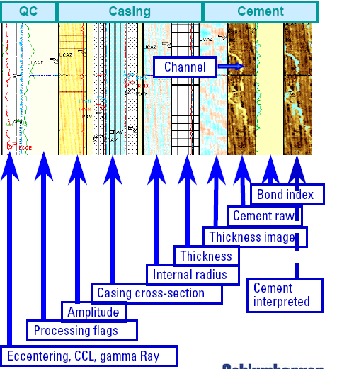
Typical USI composite presentation with casing cross section
and internal radius measurements.
CASING and TUBING INSPECTION with ELECTROMAGNETIC LOGS
 Electromagnetic
corrosion and protection evaluation tools measure casing potential and
resistance in cathodically protected wells to
evaluate protection and determine the extent of any corrosion. Using four hydraulically activated sets of
three measurement electrodes spaced at 2 foot intervals. This
service provides axial and radial current density,
corrosion rate, and casing thickness. In
wells without protection, the tool determines the rate and
location of external corrosion. Electromagnetic
corrosion and protection evaluation tools measure casing potential and
resistance in cathodically protected wells to
evaluate protection and determine the extent of any corrosion. Using four hydraulically activated sets of
three measurement electrodes spaced at 2 foot intervals. This
service provides axial and radial current density,
corrosion rate, and casing thickness. In
wells without protection, the tool determines the rate and
location of external corrosion.
This log shows
current flow in a casing string with no cathodic protection.
Corrosion is occurring at the depths shaded red. 
 Multi-frequency
electromagnetic
thickness tools are nondestructive and non-contact induction devices
to determine metal loss and changes in casing geometry, regardless of
fluid type. Generally used to find large scale
corrosion or casing splits, the tool also
detects metal loss in the outer casing of multiple casing
strings. A coil centered in the borehole generates an alternating magnetic field that interacts with
the casing; a second
coil measures phase shift. Multi-frequency
electromagnetic
thickness tools are nondestructive and non-contact induction devices
to determine metal loss and changes in casing geometry, regardless of
fluid type. Generally used to find large scale
corrosion or casing splits, the tool also
detects metal loss in the outer casing of multiple casing
strings. A coil centered in the borehole generates an alternating magnetic field that interacts with
the casing; a second
coil measures phase shift.
These electromagnetic measurements. made at multiple frequencies. are related
to casing wall thickness. inner diameter, and permeability / conductivity, Each
of these parameters is averaged around the pipe circumference.
 This composite
corrosion log run across a lost circulation zone shows the axial and
radial currents in the casing. The log shows anodic and cathodic
sections along the casing, Anodes have developed in front of the
poorly cemented section resulting in metal loss, pits, and holes. This composite
corrosion log run across a lost circulation zone shows the axial and
radial currents in the casing. The log shows anodic and cathodic
sections along the casing, Anodes have developed in front of the
poorly cemented section resulting in metal loss, pits, and holes.
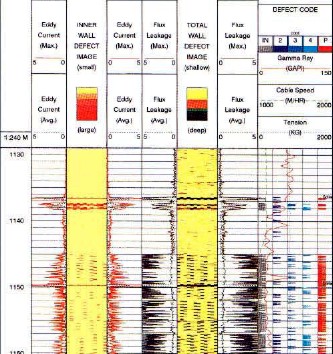 Pipe
analysis
logs monitor casing quality and discriminate
between internal and external defects. This corrosion-monitoring
service is designed primarily for detecting small holes and defects.
A high frequency eddy current test detects flaws on the inner
casing. and a magnetic flux Ieakage test inspects the full casing
thickness. With these measurements. small defects and corroded areas
in pipe are detected. and defects on the inner and outer walls of a
single casing string can he identified. Twenty-four sensor signals (12
flux
and 12 eddy) are digitally recorded for complete surface processing.
When combined with other services. severe corrosion and defects can
be detected and identified on the inner or outer pipe in a double
casing string. Pipe
analysis
logs monitor casing quality and discriminate
between internal and external defects. This corrosion-monitoring
service is designed primarily for detecting small holes and defects.
A high frequency eddy current test detects flaws on the inner
casing. and a magnetic flux Ieakage test inspects the full casing
thickness. With these measurements. small defects and corroded areas
in pipe are detected. and defects on the inner and outer walls of a
single casing string can he identified. Twenty-four sensor signals (12
flux
and 12 eddy) are digitally recorded for complete surface processing.
When combined with other services. severe corrosion and defects can
be detected and identified on the inner or outer pipe in a double
casing string.
PAL log recorded
to evaluate casing corrosion. Perforations are at 1145 to 1160 ft,
and perforations that have been squeeze cemented are at 1165 to 1167
and to 1190 fl.
fs
CASING and TUBING INSPECTION with MULTI-FINGER CALIPERS
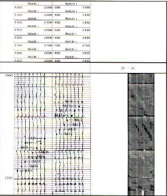 Tubing
geometry logs are multi-finger calipers, used to precisely measure variations in
the internal diameter of the tubing and to provide data for collar
corrosion analysis. The spherical lips of the caliper~ exert only 2
kg of contact force, thereby avoiding damage to pipe coatings.
Interchangeable fingers permit corrosion monitoring over a
wide range of tubing sizes. Each set of feelers can be opened and
closed downhole for repeat passes over the zone of interest. Each
of the 16 sensors generates an independent signal recorded versus
depth and both well site and computed products are available. Tubing
geometry logs are multi-finger calipers, used to precisely measure variations in
the internal diameter of the tubing and to provide data for collar
corrosion analysis. The spherical lips of the caliper~ exert only 2
kg of contact force, thereby avoiding damage to pipe coatings.
Interchangeable fingers permit corrosion monitoring over a
wide range of tubing sizes. Each set of feelers can be opened and
closed downhole for repeat passes over the zone of interest. Each
of the 16 sensors generates an independent signal recorded versus
depth and both well site and computed products are available.
Multi-finger tubing caliper
with grey scale caliper map - white is 4.0 inches, black is 4.5
inches.
Multi-finger casing caliper logs
are mechanical casing inspection devices.
Using from 36 to 72 fingers. depending on the diameter to be
measured. The tool gives very high resolution, radially and
vertically, to identify casing corrosion ranging from small pits and
scale to axial splits. The tool can be opened and closed downhole. Radii measurements include three minimum
and three
maximum (one each per 120-degree section) or six maximum (one each
per 60-degree section). All raw data and computations are available
at the well site.
CASE HISTORY: CASING INSPECTION
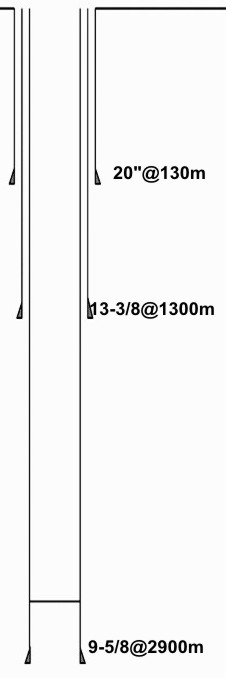 This
example combines both cement integrity and casing integrity issues.
The problem is to determine where a water flow behind casing is
coming from. The first thing you need is a a well diagram to see
what plumbing is in place, as shown at the right. The water flow is
coming up between the 9-5/8 and 13-3/8 inch casing strings. The only
water can get there is through poor quality cement behind the 9-5/8"
casing OR through a leak in the 13-3/8" casing combined with poor
cement behind that casing string. This
example combines both cement integrity and casing integrity issues.
The problem is to determine where a water flow behind casing is
coming from. The first thing you need is a a well diagram to see
what plumbing is in place, as shown at the right. The water flow is
coming up between the 9-5/8 and 13-3/8 inch casing strings. The only
water can get there is through poor quality cement behind the 9-5/8"
casing OR through a leak in the 13-3/8" casing combined with poor
cement behind that casing string.
Well diagram
showing casing sizes and depths
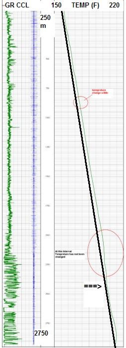 The
cheapest logs to check for water flow are noise logs and temperature
logs. In this well a temperature log was run. Water inflow might
show a slight low temperature at the point of entry, caused by gas
released from solution, with a small high temperature anomaly above
geothermal gradient, as the warm water moves upward through cooler
horizons. This water flow is 100 bbl/day, so it is significant
enough to cause such an anomaly. The
cheapest logs to check for water flow are noise logs and temperature
logs. In this well a temperature log was run. Water inflow might
show a slight low temperature at the point of entry, caused by gas
released from solution, with a small high temperature anomaly above
geothermal gradient, as the warm water moves upward through cooler
horizons. This water flow is 100 bbl/day, so it is significant
enough to cause such an anomaly.
Compressed vertical scale
temperature log. Dark diagonal line is a constant gradient. Coolest
temperature is at large arrow, with a warm spot above it (circled)
reverting to geothermal gradient above suspected entry point.
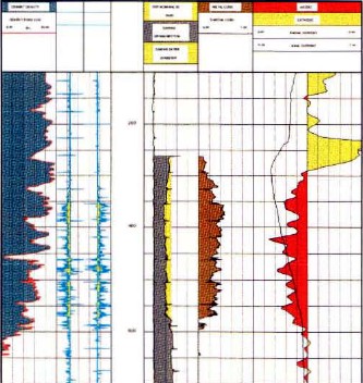
The illustration below is a casing inspection log showing good
casing at this depth. The casing ID and OD are normal and the map
shows no breaks or holes. Since water is not entering this casing
string, the log merely confirms our understanding of the situation.
Below that is an illustration of the cement integrity log, showing a
large cement channel with only about 50% of the annulus filled with
cement. While the cement is well bonded, it does not provide
isolation, and this problem persists throughout the well bore.
A cement squeeze to
fill this channel is needed. The interval should be re-logged after
the squeeze to verify isolation and fill up of the annulus.
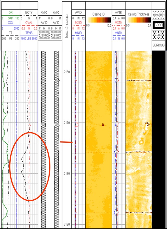
Casing inspection log over suspect area shows good casing. Ignore
the cement quality indicator on the right edge - it is just plain
WRONG - see below.
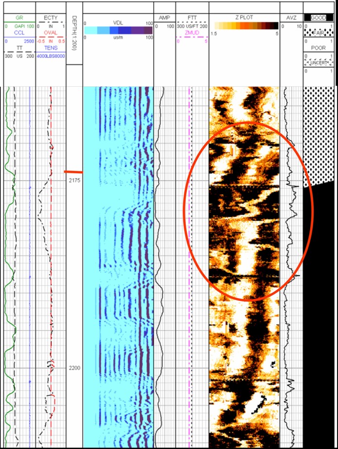
Cement integrity log over suspect interval shows a bad cement job.
White on cement map is a channel and black is good cement., giving a
Bond Index of only 50%. Water can easily flow up through such a
channel. The cement quality flag at the extreme right is WRONG
(black is supposed to represent good cement but the trigger level is
not set correctly - you need at least 80 to 90% bond for isolation
to water.
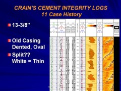
This may not be the end of the
story. The integrity of the intermediate casing also needs to be
checked. Fortunately, casing and cement logs were run before the
well was drilled to total depth. Samples are shown below. Lots of
corrosion both inside and outside the casing is indicated, possibly
because this was re-used casing. Kinks and dents are also evident on
the casing ID map. The cement fill up is also poor and a remedial
squeeze job should have been performed before the well was deepened.
There is one anomaly on the casing that might indicate a split (see
below.. There is no easy way to squeeze behind this casing now and
the temperature log is too insensitive to confirm a water leak at
this depth. The salinity of the water flowing in the annulus might
provide a clue as to whether the water is coming from a deep or
shallow source.
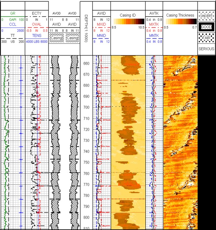
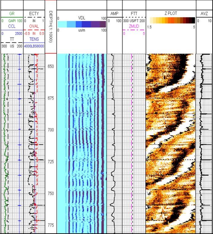
Casing profile shows corrosion an inside and outside of pipe. Map of
inside diameter shows casing is oval - dark red is large diameter,
pale colour is small diameter. Casing thickness shows possible
splits (white diagonal areas with dark blobs- white is thin, black
is thick). "Good" cement flag at far right is not correct - see
image below.
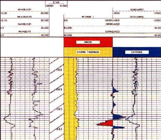
Cement bond and cement map show poor bond with a medium size channel
and no bond to the formation If the casing is split as indicated in
the previous image, this cement could allow water inflow between
this casing string and the liner. Note that the apparent "casing
splits" on the casing log are at the same place as the missing
cement. The interpretation of a casing split here is not certain -
an electromagnetic pipe evaluation tool would have been needed to
confirm.
|