The casing collar locator (CCL) was quickly added to the GR tool and this became the standard for depth control. Slim hole tools (1-11/16 inch) are used for through tubing, hostile environments in open hole, or in small diameter strat holes. Full size tools (3-7/8 inch) are used in cased or open hole applications.
In the mid 1940s, the neutron log was added. It could record through
casing, tubing, or open hole. It assisted in correlation and was a
porosity indicating log.
The pulsed neutron (thermal decay time, TDT) also followed in the
1970s, as did the natural gamma ray spectral log. With these, we
could now assess porosity and water saturation through casing, at
least in favourable conditions.
>>>> Neutron Logs The modern logs that cannot be run in casing are the dipmeter, resistivity image, nuclear magnetic resonance, and SP.
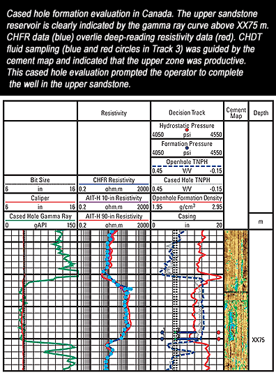
Petrophysical analysis using these cased hole reservoir measurements are processed along the same lines as with the equivalent open hole logs, with only minor exceptions. The first is that the annulus between the casing and formation must be well cemented, with good cement fill up. Most cased hole logs suffer from poor cement. A good cement bond or cement mapping log should be run and remedial action taken before running cased hole logs for reservoir evaluation.
The analyst needs to determine whether further borehole fluid,
casing size and weight, cement sheath, or other environmental
corrections are required. Some corrections are made at the time of
logging, others are not, and this varies with the age of the tool. Gamma ray tools record naturally occurring gamma rays in the formations adjacent to the wellbore. This nuclear measurement indicates the radioactive content of the formations. Effective in any environment, gamma ray tools are the standard device used for correlation of logs in cased and open holes.
■ Depth determination ■ Depth correlation within the well and between wells ■ Lithology identification ■ Qualitative evaluation of shaliness ■ Qualitative evaluation of radioactive mineral deposits ■ Cased hole perforating depth control ■ Positioning for open hole sampling tools
Spectral gamma ray tools provide insight into the mineral composition of formations. The total gamma ray spectra measured is resolved into the three most common components of naturally occurring radiation in sands and shales - potassium, thorium, and uranium (K, Th, and U, respectively). These data are used to distinguish important features of the clay or sand around the wellbore. The clay type can be determined, and sand can be identified as radioactive. The deposition of radioactive salts behind the casing by the movement of water can also be identified.
The natural gamma ray spectrometry tool uses five-window spectroscopy to resolve the total gamma ray spectra into K, Th, and U curves. The standard gamma ray (SGR) and the gamma ray minus the uranium (CGR) component are also presented. The computed gamma ray or Th curve can be used to evaluate the clay content where radioactive minerals are present.
Applications ■ Cation exchange capacity studies ■ Reservoir delineation ■ Detailed well-to-well correlation ■ Definition of facies and depositional environment ■ Igneous rock recognition ■ Recognition of other radioactive materials ■ Estimated uranium and potassium potentials ■ Lithologic analysis log input Nuclear
The effects of invasion are usually dissipated by the time the log is run, so the measurement is considered to be a good representation of true resistivity, as long as cement conditions are adequate.
The tool injects current into the casing with sidewall contact electrodes, where it flows both upward and downward before returning to the surface along a path similar to that employed by open hole laterolog tools. Most of the current remains in the casing, but a very small portion escapes to the formation. Electrodes on the tool measure the potential difference created by the leaked current, which is proportional to the formation conductivity.
Typical formation resistivity values are about 10^9 times the resistivity value of the steel casing. The measurement current escaping to the formation causes a voltage drop in the casing segment. Because the resistance of casing is a few tens of micro ohms and the leaked current is typically on the order of a few mill amperes, the potential difference measured by the CHFR-tool is in nano volts.
■ Resistivity measurement behind casing in new or old wells ■ Reservoir monitoring ■ Location of bypassed hydrocarbons ■ Determination of residual oil saturation ■ Contingency logging in wells where openhole logs could not be run ■ Primary evaluation where openhole logging is not possible Resistivity Logging
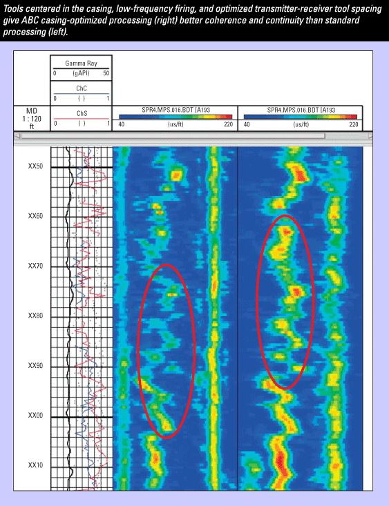
Dipole shear sonic coupled with automated sonic waveform processing for slowness determinations, provides accurate formation compressional and shear slowness measurements in cased wells. Slowness processing is based on optimally designed frequency filters and advanced signal processing. This method significantly attenuates casing arrivals to facilitate the clean extraction of formation slowness.
The dipole shear sonic log combines monopole and dipole sonic acquisition capabilities. The transmitter section contains a piezoelectric monopole transmitter and two electrodynamic dipole transmitters perpendicular to each other. An electric pulse at sonic frequencies is applied to the monopole transmitter to excite compressional- and shear-wave propagation in the formation. For Stoneley wave acquisition, a specific low-frequency pulse is used. The dipole transmitters are also driven at low frequency to excite the flexural wave around the borehole.
The tool is made up of three sections: acquisition cartridge, receiver section, and transmitter section. An isolation joint is placed between the transmitter and receiver sections to prevent direct flexural wave transmission through the tool body. The receiver section has an array of eight receiver stations spaced 6 inches. [15 cm] apart and 9 ft (2.74 m) from the monopole transmitter, 11 ft (3.35 m) from the upper dipole transmitter, and 11.5 ft (3.50 m) from the lower dipole transmitter. Each receiver station consists of two pairs of wideband-piezoelectric hydrophones aligned with the dipole transmitters.
Summing the signals recorded by one pair of hydrophones provides the monopole waveform, whereas differentiating them cancels the monopole signal and provides the dipole waveform. When a dipole transmitter is fired, the hydrophone pair diagonally in line with the transmitter is used. Four sets of eight waveforms can be acquired from the four basic operating modes fired in sequence. A special dipole mode enables recording both the inline and crossline (perpendicular) waveforms for each dipole mode. This mode, called both cross receivers (BCR), is used for anisotropy evaluation.
Applications ■ Geophysics – Velocity calibration, time/depth conversion – Synthetic seismograms – Amplitude variation with offset (AVO) calibration – Shear seismic interpretation ■ Anisotropy ■ Petrophysics – Porosity estimation (also in cased hole) – Lithology and clay identification – Gas identification ■ Stoneley wave measurement – Fracture evaluation – Permeability (mobility) ■ Geomechanics – Pore pressure – Wellbore stability – Hydrofracture design – Sand strength ■ Sonic imaging ■ Sonic imaging with borehole acoustic reflection survey (BARS) – Very long spacing tool (using spacers) – Reflection analysis – Highly dipping beds – Horizontal wells (apparent dip > 45°) – Well placement with respect to cap rock
Cased hole formation density logs make accurate formation density measurements in cased wells. A chemical gamma ray source and three-detector measurement system are used to make measurements in a wide range of casing and borehole sizes. The density measurement made by the three detector system is corrected for casing and cement thickness.
The density data are used to calculate porosity and determine the lithology. The combination of density and neutron data is used to indicate the presence of gas.
■ Porosity determination ■ Lithology analysis and identification of minerals ■ Gas detection ■ Hydrocarbon density determination ■ Shaly sand interpretation ■ Rock mechanical properties calculations ■ Determination of overburden pressure ■ Synthetic seismogram for correlation with seismic
The large yield of the neutron source enables the use of epithermal neutron detection and borehole shielding. As a result, the porosity measurements are affected only minimally by the borehole environment and formation characteristics, such as lithology and salinity. Five detectors provide information for porosity evaluation, gas detection, shale evaluation, improvement of the vertical resolution, and borehole correction. The measurements can be performed in both cased and open holes.
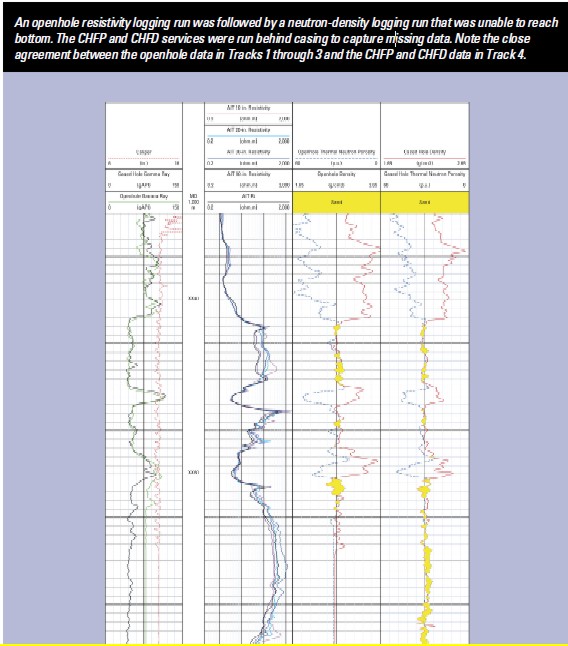
Compensated neutron logs have traditionally been run as a porosity indicator in cased wells. Although it provides a good estimation of formation porosity in most conditions, the unfocused nature of the CNL log does not allow correction for environmental effects, such as thickness of casing and cement, or effects resulting from the position of the tool and casing in the borehole. For the highest possible accuracy, CHFP service is the measurement of choice.
Compensated neutron tools measure the hydrogen index of downhole formations. The measurements are converted to porosity values, which in combination with density tool measurements provide an indication of lithology and gas in zones of interest. Some compensated neutron tools provide thermal and epithermal measurements. Thermal measurements require a liquid filled borehole. Epithermal measurements can be made in air or gas filled boreholes.
The compensated neutron log tool contains a radioactive source that bombards the formation with fast neutrons. The neutrons are slowed, primarily by hydrogen atoms in the formation. Detectors count the slowed neutrons deflected back to the tool. Because the tool responds primarily to the hydrogen content of the formation, the measurements are scaled in porosity units. Both epithermal (intermediate energy) neutrons and thermal (slow) neutrons can be measured depending on the detector design. These tools use two thermal detectors to produce a borehole-compensated thermal neutron measurement.
The dual-energy neutron log has two thermal and two epithermal detectors that make separate energy measurements for gas detection and improved reservoir description.
Applications ■ Porosity determination ■ Lithology identification ■ Gas detection ■ Correlation in cased wells ■ Option to pump slim tools down drill pipe ■ Formation evaluation behind casing ■ Accurate hydrogen index estimation ■ Clay analysis
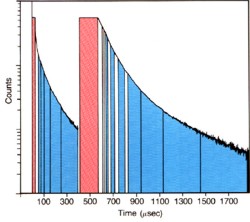
The Schlumberger TDT-M system utilizes sixteen time gates and one of four possible neutron burst widths and burst repetition rates. Counts from the sixteen gates are combined to form two "sum" gates (plus a background gate) from which SIGMA is computed. As in the TDT-K system, the combination of gates used to form the "sum" gates, as well as the burst width and repetition rate, are selected according to SIGMA (or TAU) of the formation. Because borehole diffusion is mainly a constituent of the near detector counts, this configuration allows SIGMA to be calculated preferentially using the far detector, giving a more accurate formation SIGMA. Two processing methods are possible: a real-time, single component wellsite method, and an offsite VAX model, in which 2 components are fitted independently; the offsite result is deemed accurate when the dual component results are in agreement. The wellsite model provides the initial SIGMA formation values to the offsite model. In general, the wellsite model is sufficient for monitoring water movement but the offsite model is recommended in heterogeneous or unknown lithologies, (e.g. having shales, clays or anhydrite), or in complex borehole geometries. The improved precision of the offsite model makes it a better choice for critical operations such as Log-Inject-Log.
Other service companies offer similar
tool designs. Applications ■ Formation evaluation behind casing ■ Sigma and porosity measurements.
■ Water saturation evaluation in new wells
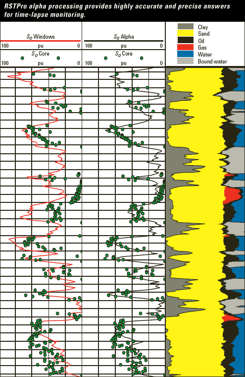
In formations with high-salinity formation water, the sigma measurement has been used for several decades to determine water saturation. The C/O ratio measurement can accurately evaluate water saturation in moderate to high porosity formations regardless of water salinity. This calculation is particularly helpful if the water salinity is low or unknown. If the salinity of the formation water is high, the Dual-Burst Thermal Decay Time measurement is used. A combination of both measurements can be used to detect and quantify the presence of injection water of a different salinity from that of the connate water.
Time-lapse measurements of water saturation can be used to monitor the performance of a well or reservoir over time. TDT logs have gone through many evolutionary changes over the years so reservoir monitoring is difficult, especially in low porosity reservoirs. Some age related normalization and bore hole corrections are often needed to makes sense of the data.
Applications ■ Formation evaluation behind casing ■ Sigma, porosity, and carbon/oxygen measurement in one trip in the wellbore ■ Water saturation evaluation in old wells where modern openhole logs have not been run ■ Measurement of water velocity inside casing, irrespective of wellbore angle (production logging) ■ Measurement of near-wellbore water velocity outside the casing (remedial applications) ■ Formation oil volume from C/O ratio, independent of formation water salinity ■ Capture yields (H, Cl, Ca, Si, Fe, S, Gd, and Mg) ■ Inelastic yields (C, O, Si, Ca, and Fe) ■ Borehole salinity
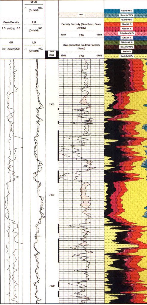
Elemental capture spectroscopy logs use a standard americium beryllium (AmBe) neutron source and a large bismuth germinate (BGO) detector to measure relative elemental yields based on neutron-induced capture gamma ray spectroscopy. The primary elements measured in both open and cased holes are for the formation elements silicon (Si), iron (Fe), calcium (Ca), sulfur (S), titanium (Ti), gadolinium (Gd), chlorine (Cl), barium (Ba), and hydrogen (H).
Wellsite processing uses the 254 channel gamma ray energy spectrum to produce dry-weight elements, lithology, and matrix properties. The first step involves spectral deconvolution of the composite gamma ray energy spectrum by using a set of elemental standards to produce relative elemental yields. The relative yields are then converted to dry-weight elemental concentration logs for the elements Si, Fe, Ca, S, Ti, and Gd using an oxides closure method.
Matrix properties and quantitative dry-weight lithologies are then
calculated from the dry-weight elemental fractions using the
SpectroLith* empirical relationships derived from an extensive core
chemistry and mineralogy database. The calculated outputs are – total clay – total carbonate – anhydrite + gypsum from S and Ca – QFM (quartz + feldspar + mica) – pyrite – siderite – coal – salt ■ matrix properties (from elements) – matrix grain density – matrix thermal and epithermal neutron – matrix sigma. Applications ■ DecisionXpress* integrated petrophysical analysis ■ Clay fraction independent of gamma ray, spontaneous potential, and density neutron ■ Carbonate, gypsum or anhydrite, pyrite, siderite, coal, and salt fractions for complex reservoir analysis ■ Matrix density and matrix neutron values for more accurate porosity calculation ■ Sigma matrix for cased and openhole sigma saturation analysis ■ Mineralogy-based permeability estimates ■ Quantitative lithology for rock properties modeling and pore pressure prediction from seismic data ■ Geochemical stratigraphy (chemostratigraphy) for well-towell correlation ■ Enhanced completion and drilling fluid recommendations based on clay versus carbonate cementation ■ Coalbed methane bed delineation, producibility, and in situ reserves estimation
|
|
||
|
Page Views ---- Since 01 Jan 2015
Copyright 2023 by Accessible Petrophysics Ltd. CPH Logo, "CPH", "CPH Gold Member", "CPH Platinum Member", "Crain's Rules", "Meta/Log", "Computer-Ready-Math", "Petro/Fusion Scripts" are Trademarks of the Author |
|||

|
||
| Site Navigation | TOOL PROFILES THROUGH CASING LOGS | Quick Links |